This topic applies to the following Generation Mode:
UHR MU PPDU
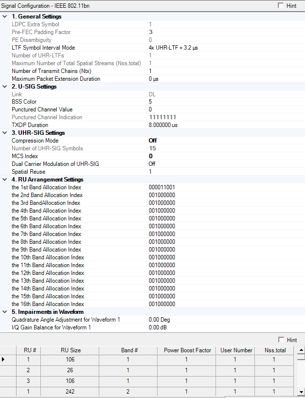
Click on a property in the image to jump to its description.
Indicates the presence of the extra OFDM symbol for LDPC.
Get the Pre-FEC Padding Factor.
Gets or sets the PE Disambiguity subfield.
Select the Symbol interval (with guard interval) for the UHR-LTF field.The possible options are 2x UHR-LTF + 0.8 us, 2x UHR-LTF + 1.6 us , 4x UHR-LTF + 3.2 us and 4x UHR-LTF + 0.8 us.
Specify the number of UHR-LTFs. If Maximum Number of Total Spatial Streams is 1, then its value is 1, otherwise its value is the ceiling of (NumOfTotalSpatialStreams / 2.0) * 2.
Get the maximum Number of Total Spatial Streams in all Resource Units.
Set the number of transmit chains. When the number of instruments is more than 1, it automatically equals to the number of instruments and can't be changed, otherwise, it's editable.
Set or Get the Maximum Packet Extension Duration for Current PPDU.An UHR PPDU may have a Packet Extension (PE) field appended at the end of the PPDU, with possible durations being 0 us, 8 us, 16 us or 20 us. The PE field, when present, shall be transmitted with the same average power as the Data field, and its content is arbitrary.
Indicates whether the frame is Uplink or Downlink. The field is set to DL for TDLS and set to UL for UHR TB PPDU.
Get or Set the Base station identifier.The BSS Color field is an identifier of the BSS.
Range:
80 MHz bandwidth: 0 to 4
160 MHz bandwidth: 0 to 12
320 MHz bandwidth: 0 to 24
Get or set the value of punctured channel pattern for non-OFDMA.
Indication of the punctured channel pattern for non-OFDMA. Each character represents 20MHz for the 80M/160M bandwidth, and 40MHz for the 320 bandiwdth. 'x' means punctured and '1' means not.
Set or Get the remaining time duration in the current TXOP. Set to 8449 μs to indicate no duration information. Set to value other than 8449 μs to indicate the duration information for NAV setting and protection of the TXOP. When the value ranges from 0 to 504 μs, the granularity is 8 μs. When the value ranges from 512 to 8448 μs, the granularity is 128 μs.
Choices: On | Off
Default: On
This compression bit is carried in the U-SIG to differentiate non-OFDMA from OFDMA PPDU. When enabled it indicates non-OFDMA PPDU.
Get the number of UHR-SIG symbols. Its minimum value is 1 and default value is 2.
Select the MCS Index of UHR-SIG. Only MCS0, MCS1, MCS3 are supported.MCS15 is equivalent to MCS0 with DCM enabled.
Enable/disable Dual Carrier Modulation for payload. It is enabled only for MCS0.
Indication of CCA Level, Interference Level accepted, TX Power.
Refer to the 802.11bn RU Allocation Subfield table to configure the 20-MHz band allocation index values.
Range: 000000000 to 111111111
Default (1st Band): 000011001
Default (2nd-16th Band): 001000000
Gets or sets the RU allocation index for the 1st 20MHz subband. It may contain multiple small-size RUs/MRUs or a large-size RU/MRU that may span multiple 20MHz subbands including the current subband. RU allocation bits 000011010 represent a punctured 242-tone RU.
Range: -90 to 90 degrees
Set the baseband quadrature angle adjustment for Waveform 1 before channel fading and mirror spectrum.
The number of parameter groups depends on Number of Transmit Chains (Ntx). Each group is identified with an incremented waveform number, such as Waveform 1, Waveform 2, and so on.
Range: -10 to 10 dB
Set the baseband IQ gain balance for Waveform 1 before channel fading and mirror spectrum.
The number of parameter groups depends on Number of Transmit Chains (Ntx). Each group is identified with an incremented waveform number, such as Waveform 1, Waveform 2, and so on.
The index for each Resource Unit of current resource unit allocation per 20 MHz .
Get the RU/MRU size.
The instrument must have at least the equivalent bandwidth to allow the waveform to be successfully transmitted.
Get the index of the first 20 MHz subband where the RU/MRU is located.
Power boost factor of current RU.
Get the number of users of current Resource Unit.
This is information indicating the total number of spatial streams of current resource unit (RU), which is equal to the sum of the Nss for each user.